
|
|
| Elliott Sound Products | Project 06 |

R8 (L&R) may be changed to 750 ohms (a standard E24 value), and C4 (L&R) changed to 100nF. If 750 ohms is not available from your supplier, use 2 x 1k5 resistors in parallel.
The phono preamp shown has an accurate RIAA equalisation curve, is very quiet, and offers far better sonic performance than the vast majority of those seen in magazines and application notes. Like most other ESP projects, it is very tolerant of opamps but the NE5532 dual op-amp is a good choice. This is a low noise, high speed device with excellent characteristics, and is inexpensive. It is ideally suited to this sort of application. Noise is extremely low, since any amplifier stage noise is rolled off above 2kHz with the passive filter. Another excellent opamp is the OPA2134, and these are used in my own units.
One factor often overlooked with phono preamps is the capacitive loading on the opamp output at high frequencies. This is all but eliminated in this design, and since the NE5532 and OPA2134 can both drive a 600 ohm load with ease, the 820/750 ohm output resistor isolates the output stage from any capacitive loading. The first stage has 10k in series with the cap, so capacitive loading is not an issue.
Note that if a moving-coil phono cartridge is to be used, a step-up transformer or ultra low-noise preamplifier circuit is needed before the phono preamp. This circuit is intended for use with the standard moving magnet type phono pickup.
Figure 1 - Phono Preamplifier (RIAA Equalisation)
The cartridge loading capacitor marked * (CLL, and its equivalent on the right channel - CLR) is entirely optional. In almost all cases, it isn't needed, because the cable capacitance between the phono cartridge headshell and the preamp will be (more than) sufficient. Some manufacturers specify a loading capacitance, but many do not. The vast majority of phono cartridges perform at their best with the lowest possible capacitance, and adding more rarely makes things better. Few people have the ability to measure the capacitance of their interconnects or the internal tonearm cables, but it's usually in the vicinity of 100pF with typical cables. Should the cartridge maker suggest a higher capacitance, feel free to experiment with the value of CLL/R. It's best to locate these caps (if used) directly across the RIAA input sockets, rather than on the PCB, and for this reason there is no provision for the loading caps on the board. The caps also should be matched so the Left and Right channels remain properly balanced.
 | There
is some debate on the Net about cartridge loading impedance, with
various suggestions that
reducing the standard load from 47k to something lower (even as low as
10k) provides benefits. While this is plausible, I've not run any tests
so cannot confirm or deny that there may be an advantage. If this is
something you wist to try, I suggest that it be done at the phono RCA
input
socket (along with the capacitor if you want to try that too). In general, I'd like to think that after all these years, the cartridge manufacturers would have a pretty fair idea of what they are doing. On that basis, I suggest that if you wish to experiment, do so by all means, but don't expect to get any 'magic' results. Bear in mind that any additional parts will also increase the input capacitance of the circuit, so you can easily end up much worse off than if you just left the circuit alone. See Phono Cartridge Loading for more information. |
The high value capacitors could be non-polarised electrolytic types, since they will have (virtually) no DC voltage across them. However, these are quite large, and standard electrolytics or even tantalum capacitors may be used instead. Polarised caps will function normally without DC bias, but tantalum is my least favourite capacitor type, and isn't recommended. Standard aluminium electrolytics are actually perfectly alright with no bias (despite what you may read elsewhere), and if sufficiently large (in value) will contribute virtually no measurable distortion. The AC voltage across C3L/R and C4L/R will never exceed ~5mV at any frequency down to 10Hz, and these caps play no part in the equalisation process. Feel free to increase the value if you wish (100uF is not a problem).
The low value capacitors should be 2.5% tolerance if obtainable, otherwise you may be able to measure a selection of standard tolerance caps to find those which are closest to the required value. Some deviation from the ideal RIAA equalisation curve will occur if these caps are too far from the designated values. More important is matching between channels - this should be as accurate as possible.
Resistors (as always) should be 1% metal film for close tolerance and low noise. This design differs from most in that the low and high frequency equalisation are performed separately, with the LF being active and the HF passive. Because of the low value of the output resistor, a following stage input impedance down to 22k will cause little degradation of the EQ curve.
The customary "flattening" of the curve at 50Hz has not been fully incorporated, since most listeners find that the bass sounds far more natural without this. In this respect it can be said that accuracy is lacking, but I am still using this arrangement, and have not found rumble or other low frequency 'noise' to be a problem.
Based on the RIAA specification, the table shows the performance with frequency - below 50Hz there is a marked (and deliberate) deviation, and 'accuracy' figures are not quoted.
Note that there is no provision for a 'rumble' (subsonic) filter, and the circuit as shown has a low frequency -3dB point of about 3Hz. A low rumble turntable is essential - especially if you use a subwoofer. A well damped and isolated turntable platform is an excellent idea, and I have had great success with a large concrete paving slab, neatly covered with speaker carpet or other material, and isolated using foam rubber. Some experimentation will be needed to get this exactly right. Usually, good results will be obtained when the foam support is compressed to 70% of its normal thickness with the weight of the concrete slab and turntable. A shelf attached to a wall is another good method of providing subsonic isolation.
If low-frequency noise is a problem, you will often see vigorous movement of the woofer cones even when there is no bass content. If this is an issue with your setup, I recommend that you include a Project 99 subsonic filter. The standard configuration is 36dB/octave, with a -3dB frequency of 17Hz. This will normally eliminate even the most intractable low frequency interference, typically caused by warped discs. It usually helps if you have LF feedback problems too, but they have to be below the cutoff frequency of the filter.
| Freq - Hz | Gain - dB | Ideal - dB | Error - dB |
| 20 | 62.25 | N/A | N/A |
| 50 | 59.16 | 58.42 | 0.74 |
| 500 | 43.87 | 44.42 | -0.55 |
| 1000 | 41.42 | Reference | |
| 2100 | 38.88 | 38.42 | 0.46 |
| 21 k | 22.17 | 21.42 | 0.75 |
As can be seen from the table, accuracy is better than 1dB, and gain at 1kHz is about 40dB (100) so a nominal 5mV cartridge output will give 500mV output. This may be increased if necessary, by increasing the value of the 100k resistor in the second stage. Care is needed to ensure that the gain is not increased so far as to cause clipping of the signal - allowing for the worst possible case. As it stands, stage 2 has a gain of 38 (31dB).
If the 100k resistor were to be increased to 220k, the total gain will be slightly more than doubled, at 38dB. An input signal to stage 2 at 17mV (5mV phono cartridge output) gives a normal output at 1kHz (before the passive filter) of 1.12V RMS. The theoretical output at 20kHz is over 9.75V RMS, but this never happens because at 20kHz all recordings will be 15-20dB below the level at 1kHz (being very conservative). See Audio Level Vs. Frequency, below. This means that actual output level at 20kHz will typically be around 1V RMS at the most. However, if the gain of the second stage is increased too far, there is a risk of clipping. This is an unlikely possibility due to the nature of music - there are very few fundamental frequencies of any instrument (other than a synthesiser) above 1kHz, and most harmonics roll off naturally at approximately 3 to 6dB per octave above about 2kHz, but it must be considered.
Only one channel is shown, the other channel uses the remaining half of each op-amp, the pinouts of which are shown on the diagram. Remember that the +ve supply connects to pin 8, and the -ve supply to pin 4.
Op-amps should be bypassed from each supply line to ground with a 10uF electrolytic and a 100nF polyester or ceramic capacitor to ensure stability.
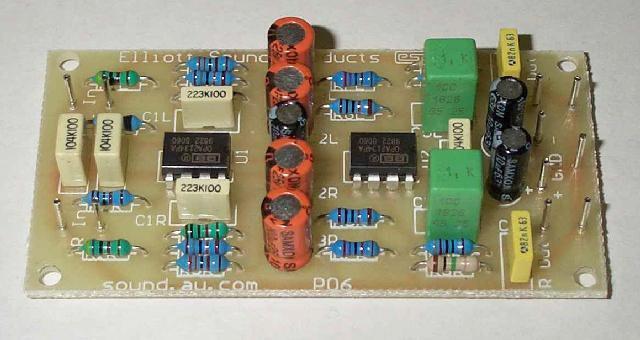
Photo of Completed Unit
The photograph above shows a complete phono preamp using the PCB. This is as shown in Figure 1, but is an early version of the board (those now available look much nicer).
A large proportion of P06 PCB sales are a direct result of
recommendations from others who have built it and found (as I did when I
first designed the circuit many years ago) that the overall sound is
better than the average phono preamp. There's no reason I can think of
that should make it sound any different from more conventional circuits,
but it's hard to argue with hundreds of happy customers  .
.
There is very little on the Net or elsewhere that gives anyone an idea of the level they should expect at any frequency. The image below was captured using 'Visual Analyzer' - one of many PC based FFT programs that are available. The signal was taken from an FM tuner - you can see the sharp rolloff above 15kHz and the 19kHz pilot tone used to decode the 38kHz FM sub-carrier. The capture was taken off-air, from an Australian 'alternative' radio station, so includes several different genres of music, as well as speech.
The capture was set up to hold the maximum level detected over the sample time (over 2 hours), so represents the highest level recorded at any frequency across the band. Although everything above 15kHz is removed, the overall trend is clearly visible. While there will always be deviations and exceptions with different musical styles, I have run this test before and used different programme material. The general trend is valid over a wide range of music styles. No equalisation was used on the received signal - it is captured directly off-air.
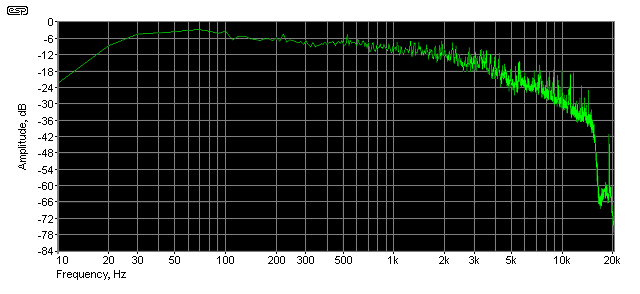
Figure 2 - Amplitude Vs. Frequency of 'Typical' Audio
The 'reference' level is -9dB at 1kHz. The maximum peak levels are seen between 30Hz and 100Hz (this is definitely programme material dependent!), and the level between 200Hz and 2kHz is reasonably flat, showing roughly 3dB fall over that frequency range. There is a ~6dB rolloff in the octave from 2k-4kHz, followed by a ~10dB rolloff between 4k-8kHz. What is of greater interest is the amplitude of the highest peaks, because overload will occur on peaks, not average levels. At 10kHz and just above, there are peaks at -18dB and some additional peaks (-24dB) at just below 15kHz.
Based on this, it's reasonable to expect that the worst case level at above 15kHz will never exceed -30dB, and this is 21dB below the level at 1kHz (a little less than 1/10th). A cartridge with 5mV output at reference level 1kHz will therefore have no more than 5mV output at any frequency around 20kHz - this is the highest level we can expect. With the recommended component values for the RIAA equaliser, the maximum possible level from the output of the second stage is around 1V RMS - well within the capabilities of the suggested opamps. Even if the maximum level were to be 50mV (same output at 20kHz as at 1kHz), the second stage is still below the clipping level. Further increases of gain are not recommended unless you understand the likely outcome.
Figure 3 - Single Supply Version
19 Sept 2008 - I have altered the original circuit modification to make it closer to the original, and to reduce the possibility of supply noise getting into the signal path. The amended drawing is shown. The components RX1, RX2 and CX1 are external to the PCB - these components can be shared with left and right channels. You will need to make the appropriate changes to the PCB to use this version. If possible, the dual supply version (as designed) is preferable and should be used unless there is abolutely no alternative. As noted on the circuit diagram, I really don't recommend this, because of the difficulty of modifying the PCB connections to ensure that the artificial earth (ground) is sufficiently stable to prevent low frequency disturbances. (Original modification submitted by Tom Windelinckx.)
 Main Index
| Copyright Notice. This article, including but not limited to all text and diagrams, is the intellectual property of Rod Elliott, and is Copyright © 1999. Reproduction or re-publication by any means whatsoever, whether electronic, mechanical or electro-mechanical, is strictly prohibited under International Copyright laws. The author (Rod Elliott) grants the reader the right to use this information for personal use only, and further allows that one (1) copy may be made for reference while constructing the project. Commercial use is prohibited without express written authorisation from Rod Elliott. |